
DSPC406
DSPC406
主营旗下三大系列:
1. ABB DCS过程控制系统
①ABB FreeLance AC800F电源模件:
SA801F/SA811F/SD802F/SD812F
PM802F/PM803F
FI810F/FI820F/FI830F/FI840F
EI811F/ABB EI812F/ABB EI813F
07KT97B/ 07AC91D
②ABB S800 IO模拟量I/O模件
AI801/ AI810/ AI825/ AO801/ AO845/ AO895
③ABB S800 IO开关量I/O模件
DI801/ DI810/ DO801/ DO810④ABB张力计
PFEA111/PFEA112
2. ABB Bailey 贝利
第一代(80年)DCS系统:Network-90
第一代(80年)DCS系统:Network-90
主营:第三代(94年)DCS系统:Infi-90 Open
IMASI23/IMHSS03/IMDS../INICI../IMRD../IE../BRC…
第四代(98年)DCS系统:Symphony
主营:第五代 最新DCS系统:
SPBRC300/SPBRC400/SPNIS21/SPNPM22
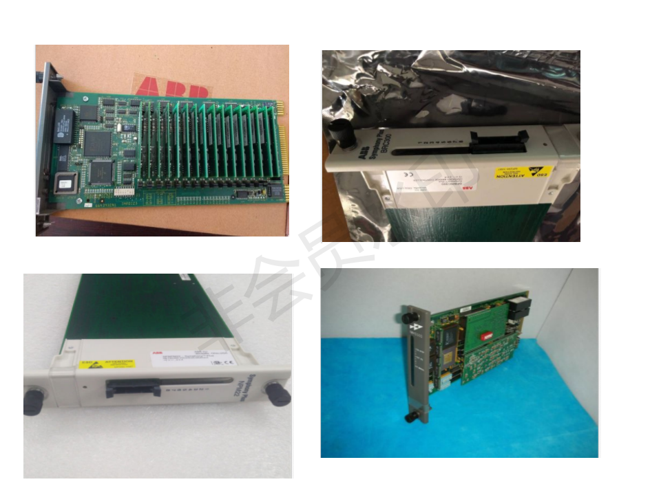
3. ABB 机器人系统
常用配件系列:DSQC…/3HAB…/3HAC…./3HAA…/3HNE….
高压变频系列:5SD……./5SHX…./5SHY……

==* 主要经营产品 *==
優勢品牌:A-B、siemens、Foxboro、ABB、schneider、triconex等國外知名DCS,PLC備件
*FOXOBORO(福克斯波罗) I/A:AW51B,P0400YC FBM02,P0400YV FBM18,FBM241C,FBM242 ,P0400ZE,
FBM04,P0914WM ,FBM217 P0914TR,P0916TA,CP40B P0961BC,FBM44 P0950BN等。
*Westinghouse(西屋):OVATION系统、WDPF系统、WEStation系统备件。
*MOTOROLA MVME系列:MVME 162、MVME 167、MVME1772、MVME177等系列。
*Honeywell(霍尼韦尔):DCS系统备件模件、Ho
*Yaskawa(安川):MOTOMAN伺服控制器、伺服马达、伺服驱动器。
*Allen Bradley(罗克韦尔): 1756/ 1771/ 1785/ 2711系例、Reliance机电等产品。
*Schneider(施耐德):MODICON 140系例、Quantum内存卡、Quantum电源模块等。
*XYCOM:XVME-103、XVME-690、VME总线等备件。
*FANUC(法那克):模块、卡件、驱动器等各类备件。
*SIEMENS(西门子):Siemens Iskamatic,Siemens Simatic S5,Siemens Simatic C1,数控系统等。
*力士乐INDARMAT:电机、伺服控制器
*各大进口品牌机器人备件:ABB, Adept, Comau, Fanuc, Kuka, Mitsubishi, Motoman, Nachi, Panasonic,OTC 系列 等Robots备件.
*其他进口品牌:DELL 通讯,SEW品牌系列,Beijer系列产品,CT 系列,Omron 品牌PLC系列,PH0ENIX 模块,Cutler-Hammer 在线销售,HP(惠普)系列,Eurotherm(欧陆)控制,Cisco(思科)网络服务,Emerson(爱默生)co
The working principle of PLC when the PLC is put into operation, its working process is generally divided into three stages, i. e. input sampling, user program execution and output refresh. The completion of these three phases is called a scan cycle. During the whole running period, the PLC's CPU repeatedly performs the above three stages with a certain scanning speed. One input sampling phase, in the input sampling phase, the PLC reads all the input states and data by scanning in turn, and stores them in the corresponding unit in the I / O Image area. After the input sample is completed, go to the user program execution and output refresh phase. In both phases, even if the input state and data change, the state and data of the corresponding unit in the I / O Map area remain unchanged. Therefore, if the input is a pulse signal, the width of the pulse signal must be greater than one scan cycle to ensure that the input can be read in any case. Two User Program Execution Stage, in User Program Execution Stage, PLC always scans user program ladder diagram in order from top to bottom. When scanning each ladder diagram, we always first scan the control circuit made up of each contact on the left side of the ladder diagram, and carry out logical operation on the control circuit made up of contact points in the order of left, right, first up, then down, then, according to the result of logical operation, the state of the corresponding bit of the logic coil in the system RAM storage area is refreshed, or the state of the corresponding bit of the output coil in the I / O Image area is refreshed; Or determine whether special functional instructions specified in the ladder diagram are to be executed. That is, only the state and data of the input point in the I / O Image region remain unchanged during the execution of the user program, the state and data of other output points and soft devices in the I / O Image area or the system RAM storage area may change, and the ladder diagram at the top, the result of the program will work on the ladder diagram below where these coils or data are used; on the contrary, the ladder diagram below, the status or data of the flushed logic coil can not affect the program on top of it until the next scan cycle. Three output refresh phase, when the end of the scanning user program, the PLC will enter the output refresh phase. During this period, the CPU refreshes all the output latches according to the corresponding state and data in the I / O Image area, and drives the corresponding peripheral via the output circuit. At this point, is the real output of PLC, the same number of ladder diagram, its sequence is different, the results of the implementation is different. In addition, the running result of the scanning user program is different from that of the hard logic parallel running of the relay control device. Of course, if the scan cycle time is negligible for the entire run, then there is no difference. Generally speaking, the scan cycle of PLC includes self-diagnosis, communication, that is, a scan cycle is equal to the sum of all time of self-diagnosis, communication, input sampling, user program execution, output refresh, etc. .
热点推荐


加载中...
猜你想搜
实时热点 3分钟前更新换一换

 客服1
客服1